FORM NO. 3319–650 Rev A Wheel Horse 48” Side Discharge Mower for Classic Garden Tractor Model No. 78361 – 8900001 & Up Operator’s Manual IMPORTANT: Read this manual carefully. It contains information about your safety and the safety of others. Also become familiar with the controls and their proper use before you operate the product.
Introduction We want you to be completely satisfied with your new product, so feel free to contact your local Authorized Service Dealer for help with service, genuine replacement parts, or other information you may require. Whenever you contact your Authorized Service Dealer or the factory, always know the model and serial numbers of your product. These numbers will help the Service Dealer or Service Representative provide exact information about your specific product.
Contents Safety and Instruction Decals . . . . . . . . . . . . . . Assembly . . . . . . . . . . . . . . . . . . . . . . . . . . . . . . Loose Parts . . . . . . . . . . . . . . . . . . . . . . . . . Installing Discharge Chute . . . . . . . . . . . . . Attach Adjustable Link . . . . . . . . . . . . . . . Installing the Mower . . . . . . . . . . . . . . . . . Front-to-Rear Blade Slope . . . . . . . . . . . . . Transport Height Adjustment . . . . . . . . . . . Removing the Mower . . . . . . . . . . . . . . . .
Safety Safety and Instruction Decals Safety decals and instructions are easily visible to the operator and are located near any area of potential danger. Replace any decal that is damaged or lost. ON GRASS DEFLECTOR (Part No. 93–1122) NEXT TO H-O-C LEVER (Part No. 106753) 2 ON MOWER LEFT AND RIGHT SIDES (Part No.
Assembly Loose Parts Note: Use the chart below to identify parts used for assembly. DESCRIPTION QTY.
Assembly Installing Discharge Chute POTENTIAL HAZARD • Without the grass deflector, discharge cover, or complete grass catcher assembly mounted in place, you and others are exposed to blade contact and thrown debris. WHAT CAN HAPPEN • Contact with rotating mower blade(s) and thrown debris will cause injury or death. HOW TO AVOID THE HAZARD • NEVER remove the grass deflector from the mower because the grass deflector routes material down toward the turf.
Assembly Attach Adjustable Link Installing the Mower 1. 1. Park the machine on a level surface, disengage the power take off (PTO), set the parking brake, and turn the ignition key to “OFF” to stop the engine. Remove the key. 2. Turn the front wheels fully to the left and raise attachment lift lever all the way to the latched position; refer to tractor Operator’s Manual. 3. Open front and mid-mount hitches by pushing release button and moving lock handles forward (Fig. 3).
Assembly 4. Slide the mower under the chassis from the right side and align attachment lift with slot in center lever bar (Fig. 4). 7. Rotate front mounting shaft so fork faces up and align so spacers are between mid-mount hitch plates (Fig. 5). 5. Straighten the front wheels, turn Dial-A-Height knob counterclockwise, all the way, and lower the attachment lift lever to the mounting position; refer to tractor Operator’s Manual. 8.
Assembly 10. Remove hairpin cotters from trunnion and bottom of yoke (Fig. 7). 2 11. Unlatch and remove locking clevis pin that secures yoke assembly to clutch shaft. Pivot yoke out and forward to remove from clutch shaft and engagement plate (Fig. 7). 3 1 m–2810 12. Place belt in inside pulley groove (Fig. 7). 13. Assemble yoke and engagement plate and attach locking clevis pin, trunnion and hairpin cotters to secure (Fig. 7). 1 2 Figure 8 1. Pulley assembly 2. Front hitch 3. Latch 15.
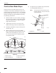
Assembly Front-to-Rear Blade Slope 5. Check the front-to-rear blade slope any time you install the mower. Before checking the slope, set air pressure in the front and rear tires to 12 psi (.85 kPa). If the front blade tip is not 1/8–1/4” (4–7 mm) lower than the rear blade tip, adjust the blade slope using the following instructions: 1. Park the machine on a level surface, disengage the power take off (PTO), set the parking brake, and turn the ignition key to “OFF” to stop the engine. Remove the key. 2.
Assembly Transport Height Adjustment Removing the Mower Transport height is adjusted to stabilize the mower in the up, locked position. 1. Park the machine on a level surface, disengage the power take off (PTO), set the parking brake, and turn the ignition key to “OFF” to stop the engine. Remove the key. 2. Remove the two wing nuts and belt cover from the tractor (Fig. 13). 1. 2. 3. Raise attachment lift lever all the way to the latched position.
Assembly 4. Remove hairpin cotters from trunnion and bottom of yoke (Fig. 15). 9. Raise attachment lift lever to the mounting position; refer to tractor Operator’s Manual. 5. Unlatch and remove locking clevis pin that secures yoke assembly to clutch shaft. Pivot yoke out and forward to remove from clutch shaft and engagement plate (Fig. 15). 10. Open mid-mount hitch lock handle. Lower mower with attachment lift and remove front mounting shaft (Fig. 17). 6. Remove belt from pulley (Fig. 15). 7.
Operation Side Discharge POTENTIAL HAZARD • Without the grass deflector, discharge cover, or complete grass catcher assembly mounted in place, you and others are exposed to blade contact and thrown debris. WHAT CAN HAPPEN • Contact with rotating mower blade(s) and thrown debris will cause injury or death. HOW TO AVOID THE HAZARD • NEVER remove the grass deflector from the mower because the grass deflector routes material down toward the turf. If the grass deflector is ever damaged, replace it immediately.
Operation Attachment Lift Lever Attachment Power Lift The attachment lift lever (Fig. 20) is used to raise and lower various attachments. The attachment power lift (Fig. 21) is used to raise and lower attachments. Raising Attachments Raising Attachments 1. Depress the clutch and brake pedals to stop the machine. 1. Start the engine, refer to; Starting and Stopping the Engine; in tractor Operator’s Manual. 2. Pull attachment lift lever rearward until latch locks.
Operation Adjusting Height-of-Cut The rear gauge wheels are adjusted in different hole location for 1-1/2–3-1/2” (4–9 cm) height-of-cut. 1. Pull height-of-cut lever out to disengage from quadrant. Adjust height-of-cut to the desired level. Release lever inward to lock into quadrant (Fig. 22). 4 3 2 1 m–2827 Figure 22 1. Height-of-cut lever 2. Quadrant 3. Low 4.
Operation Tips for Mowing Grass Fast Throttle Setting Ground Speed To improve cut quality, use slower ground speed. For best mowing and maximum air circulation, operate the engine at “FAST.” Air is required to thoroughly cut grass clippings, so do not set the height-of-cut so low, as to totally surround the mower by uncut grass. Always try to have one side of the mower free from uncut grass, which allows air to be drawn into the mower.
Maintenance Service Interval Chart Service Operation Each Use Cutter Blade—check 5 Hours 25 Hours X X Grease–Mower spindles, wheels X Belts—check for wear/cracks Mower Housing—clean Chipped Surfaces—paint 50 Hours Storage Service Notes X X X X X X X X POTENTIAL HAZARD • If you leave the key in the ignition switch, someone could start the engine. WHAT CAN HAPPEN • Accidental starting of the engine could seriously injure you or other bystanders.
Maintenance Cutting Blade To assure a superior quality of cut, keep the blade(s) sharp. For convenient sharpening and replacement, you may want to have an extra blade(s). 1 2 3 POTENTIAL HAZARD • A blade that is worn or damaged could break apart and pieces could be thrown at bystanders or at you as you use the mower. WHAT CAN HAPPEN • Pieces of blade that may be thrown could 151 Figure 23 1. Cutting edge 2. Curved area 3. Wear/slot forming seriously injure or kill you or bystanders.
Maintenance Sharpening the Blade(s) Installing the Blade(s) 1. 1. Use a file to sharpen the cutting edge at both ends of the blade (Fig. 25). Maintain the original angle. The blade retains its balance if the same amount of material is removed from both cutting edges. IMPORTANT: The curved part of the blade must be pointing toward the inside of the mower to assure proper cutting. 2. 1 Install the washer, blade, flat washer, and the blade nut (Fig. 27).
Maintenance Greasing and Lubrication Blade Drive Belt Service Interval/Specification Removing the Blade Drive Belt Grease the mower after every 50 operating hours or once a year, whichever occurs first. Grease more frequently when operating conditions are extremely dusty or sandy. 1. Remove the mower; refer to Removing the Mower, page 9. 2. Remove pulley cover mounting screws and pulley covers from both blade pulleys. 3. Push on idler to release tension and remove the belt from the pulleys (Fig.
Maintenance Power Take Off (PTO) Belt 1. 4. Unlatch and remove locking clevis pin that secures yoke assembly to clutch shaft. Pivot yoke out and forward to remove from clutch shaft and engagement plate (Fig. 32). 5. Replace belt in inside pulley groove (Fig. 32). 6. Assemble yoke and engagement plate and attach locking clevis pin, trunnion and hairpin cotters to secure (Fig. 32). Remove the two wing nuts and belt cover from the tractor (Fig. 30). 2 1 1 2 m–2534 2 Figure 30 1.
Maintenance 7. Route belt around V and flat pulleys and loop over center mower spindle, top pulley.(Fig. 33). 8. Check that spacer is on shaft and install belt cover with rod in hole. Secure with locknut (Fig. 33). 9. Turn knob counterclockwise to tighten belt (Fig. 33). Tighten until there is 1” (26 mm) belt movement between engine clutch and idler pulley when slight pressure is applied to the belt. 3 4 Clean dirt and chaff from the outside of the engine’s cylinder head fins and blower housing.
Troubleshooting PROBLEM Abnormal vibration. Blade(s) does not rotate. Uneven cutting g height. g POSSIBLE CAUSES CORRECTIVE ACTION 1. Cutting blade(s) is bent or unbalanced. 1. Install new cutting blade(s). 2. Blade mounting bolt is loose. 2. Tighten blade mounting bolt. 3. Engine mounting bolts are loose. 3. Tighten engine mounting bolts. 4. Loose engine pulley, idler pulley, or blade pulley. 4. Tighten the appropriate pulley. 5. Engine pulley is damaged. 5.