
Operator's Manual


Installation
6
Tractor
Preparation
1. Park the machine on a level surface and lower
attachment lift to the full “DOWN” position.
Refer to Operation: Attachment Lift page 14.
Note: Turn Dial-A-Height control to allow
lift to go to full “MOUNTING”
position.
2. Adjust air pressure in tires to recommended
pressure.
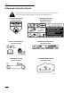
3. Adjust transport height nut until bottom of rear
lift arms are approximately 7-1/4” (188 mm)
from the level surface (Fig. 5).
2
3
1
Figure 5
1. Transport
height nut
2.
Rear lift arms
3.
7-1/4” (188 mm)
4. Raise attachment lift to the full “UP” position.
Refer to Operation: Attachment Lift page 14.
5. Remove E-ring, washer and lift link from front
lift arm (Fig. 6).
6. Hold front lift arm up until stop contacts frame
(Fig. 6).
7. Push back hard on lift rod, to raise linkage, and
check location of lift rod compared to mounting
hole location.
8. Adjust length of lift rod, by turning in\out of
trunnion, so end just slides into mounting hole in
front lift arm (Fig. 6).
9. Slide lift rod into hole and secure with
previously removed washer and E-ring (Fig. 6).
10. Check that stop is 0”–1/8” (0–3 mm) away frame
when fully assembled and lift in the full “UP”
position.
2
m–3398
4
1
3
5
Figure 6
1. E-ring
2. Washer
3. Stop
on lift arm
4.
Lift link
5. Trunnion
11. Remove bolts securing existing up-stop to
tractor frame (Fig. 7).
12. Place J-clip, holding drain hose, against frame
and mount new, long, up-stop to frame with
previously removed hardware (Fig. 7).
2
m–3390
1
3
Figure 7
1. Up-stop
(long)
2. J-clip
3.
Existing bolts