
Operator's Manual


Installation
7
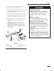
11. Unplug clutch wire terminal from tractor wire
harness and remove retainer clip (Fig 8).
Remove center retaining bolt and washer then
slide double pulley clutch off shaft (Fig. 7).
Note: Center bolt is installed with thread
locking compound, impact wrench
may be required to remove.
Note: Save hardware for use when installing
single pulley clutch.
12. Position clutch so wire points toward right front
of tractor and point of triangle is in captured
up-stop. Align key in clutch with keyway and
slide single pulley clutch onto shaft (Fig. 7).
Secure with thread locking compound on threads
of previously removed hardware.
13. Torque bolt to 55 ft-lbs. (75 N
.
m)
1
2
4
3
5
6
m-4828
Figure 7
1. Single Pulley Clutch –
Included with deck
2. Engine
3. Bolt
4. Washer
5. Clutch Plug–in
6. Upstop
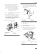
14. Install retainer clip and clutch plug–in to right
side of frame as shown in figure 8. Make sure
there is no slack in plug–in wire between clutch
and retainer clip.
1
2
3
m–4633
4
Figure 8
1. Clutch Plug–in
2. Right side of frame
3. Retainer Clip
4. Right Front Tire
15. Plug clutch plug–in into terminal of tractor wire
harness (Fig.7).
16. Remove bolts securing existing up-stop to
tractor frame (Fig. 9).
17. Place J-clip, holding drain hose, against frame
and mount new, long, up-stop to frame with
previously removed hardware (Fig. 9).
2
1
3
m–4622
4
Figure 9
1. Up-stop (long)
2. J-clip
3. Existing bolts
4. Ensure this tab is in slot in
clutch