
Service Manual


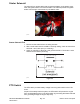


Table Of Contents
- Revision History
- Preface
- Chapter 1 : Safety
- Chapter 2 : Specifications and Maintenance
- Chapter 3 : Troubleshooting
- Chapter 4 : Engine
- Chapter 5 : Chassis
- General Information
- Service and Repairs
- Caster Fork and Bearing Replacement
- Caster Wheel Replacement
- Left Console Replacement
- Right Console Replacement
- Seat Replacement
- Fuel Tank Replacement
- ROPS (Roll Over Protection System) Replacement
- Throttle Cable Assembly Replacement
- Choke Control Assembly Replacement
- Park Brake Handle Assembly Replacement
- Adjusting the Park Brake
- Motion Control Damper
- Motion Control Assembly Replacement
- Adjusting the Motion Control Handle Position
- MYRIDE® Replacement
- Chapter 6 : Deck
- Chapter 7 : Drive System
- Chapter 8 : Electrical
- Appendix A: Foldout Drawings
- Electrical Schematic
- Kawasaki Engine Electrical Schematic

ServiceandRepairs
ElectricalAssembly1
g337720
Figure79
1.USBPowerPort8.BungeeStrap
2.ModuleAsm
9.Switch
3.IgnitionKey10.WireHarness
4.PTOSwitch
11.Battery
5.RockerSwitch
12.WireHarness
6.IgnitionSwitch13.BailSwitch
7.USBKitWireHarness
14.BatteryTray
2000SeriesZMASTER®ServiceManual
Page8–3
Electrical:ServiceandRepairs
3438-778RevA