
Service Manual


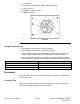


Table Of Contents
- Revision History
- Preface
- Chapter 1 : Safety
- Chapter 2 : Specifications and Maintenance
- Chapter 3 : Troubleshooting
- Chapter 4 : Engine
- Chapter 5 : Chassis
- General Information
- Service and Repairs
- Caster Fork and Bearing Replacement
- Caster Wheel Replacement
- Left Console Replacement
- Right Console Replacement
- Seat Replacement
- Fuel Tank Replacement
- ROPS (Roll Over Protection System) Replacement
- Throttle Cable Assembly Replacement
- Choke Control Assembly Replacement
- Park Brake Handle Assembly Replacement
- Adjusting the Park Brake
- Motion Control Damper
- Motion Control Assembly Replacement
- Adjusting the Motion Control Handle Position
- MYRIDE® Replacement
- Chapter 6 : Deck
- Chapter 7 : Drive System
- Chapter 8 : Electrical
- Appendix A: Foldout Drawings
- Electrical Schematic
- Kawasaki Engine Electrical Schematic

g336408
Figure90
Note:TheenginewillnotcrankoverwhenthePTOswitchisintheONposition.
ThePTOswitchprovidesbatteryvoltagefromtheignitionswitchtotheparking
brakeswitchandtheneutralswitchesaspartofthesafetyinterlocksystem.
PTOSwitchTest
1.Removethecontrolpanelfromtherightconsole.
2.DisconnectthePTOswitchfromthewireharness.
3.WiththeswitchintheONposition(buttonpulledOUT).
g336409
Figure91
4.Usingadigitalmulti-metersettotheOHMorContinuitysetting,verifythe
following:
•Pin2and5shouldhavecontinuity(closed)
•Pin1and4shouldhavecontinuity(closed)
•Pin1and7shouldNOThavecontinuity(open)
•Pin2and8shouldNOThavecontinuity(open)
5.WiththeswitchintheOFFposition(buttonpushedIN):
•Pin1and7shouldhavecontinuity(closed)
•Pin2and8shouldhavecontinuity(closed)
Electrical:ServiceandRepairs
Page8–10
2000SeriesZMASTER®ServiceManual
3438-778RevA