
Service Manual


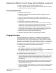


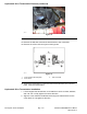


Table Of Contents
- Revision History
- Preface
- Chapter 1 : Safety
- Chapter 2 : Specifications and Maintenance
- Chapter 3 : Troubleshooting
- Chapter 4 : Engine
- Chapter 5 : Chassis
- General Information
- Service and Repairs
- Caster Fork and Bearing Replacement
- Caster Wheel Replacement
- Left Console Replacement
- Right Console Replacement
- Seat Replacement
- Fuel Tank Replacement
- ROPS (Roll Over Protection System) Replacement
- Throttle Cable Assembly Replacement
- Choke Control Assembly Replacement
- Park Brake Handle Assembly Replacement
- Adjusting the Park Brake
- Motion Control Damper
- Motion Control Assembly Replacement
- Adjusting the Motion Control Handle Position
- MYRIDE® Replacement
- Chapter 6 : Deck
- Chapter 7 : Drive System
- Chapter 8 : Electrical
- Appendix A: Foldout Drawings
- Electrical Schematic
- Kawasaki Engine Electrical Schematic

AdjustingtheMotionControlLinkage(NeutralSetting)(continued)
g336201
Figure72
1.Nut
1.Priortostartingtheengine,pushthedeckliftpedalandremovethe
height-of-cutpin.Lowerthedecktotheground.
2.Raisetherearofthemachineupandsupportwithjackstands(orequivalent
support)justhighenoughtoallowdrivewheelstoturnfreely.
3.Removetheelectricalconnectionfromtheseatsafetyswitch,locatedunder
thebottomcushionoftheseat.
Note:Theseatsafetyswitchisapartoftheseatassembly.
4.Temporarilyinstallajumperwireacrosstheterminalsintheconnectorof
themainharness.
5.Starttheengine.Runtheengineatfullthrottleandreleasetheparkingbrake.
Note:Ensurethattheparkingbrakeisengagedandthatthemotioncontrol
leversareinneutral(out)tostarttheengine,theoperatordoesnothaveto
bepresentintheseat.
6.Runthemachinefor5minuteswiththedriveleversinthefullforwardspeed
tobringhydraulicuiduptooperatingtemperature.
7.Bringthemotioncontrolleversintotheneutralposition.
Note:Themotioncontrolleversmustbeinneutralwhilemakingany
necessaryadjustments.
8.Checkandensurethatthecontrolplatetabstouchthereturn-to-neutral
platesonthehydraulicunits.
9.Adjustthepumpcontrolrodlengthsbyturningthenut(A)intheappropriate
directionuntilthewheelsslightlycreepinreverse.
10.Movethemotioncontrolleverstothereversepositionwhileapplyingslight
pressuretothelever.Allowtheneutralreturnspringstobringthelevers
backtoneutral.
Note:Thewheelsmuststopturningorslightlycreepinreverse.
11.Shutoffthemachine.
12.Removethejumperwirefromthewireharnessandplugtheconnectorinto
theseatswitch.
13.Lowertheunit.
DriveSystem:ServiceandRepairs
Page7–6
2000SeriesZMASTER®ServiceManual
3438-778RevA