
Service Manual


XL Lawn Tractor Service Manual 6 - 19
MOWER
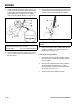
8. Move the height-of-cut lever (deck lift) into the “A”
notch.
Figure 234
1851
9. Check that both rods extend 5/8” (16mm) beyond
adjustment block (Figure 235).
10. Slide the end of the long rod through the hole in
the mower mount (Figure 235). Install the thin
washer and hairpin cotter to secure the rod in
place. Repeat this step on the opposite side of the
mower.
11. Mount the slotted mower leveling bracket onto the
pin on the mower mount (Figure 235). Install the
thick washer and hairpin cotter to secure the
mower. Repeat this step on the opposite side of
the mower.
Figure 235
1805
12. Look under tractor and take down blade control
(PTO) cable nested inside frame rail.
13. Thread first jam nut onto the blade control (PTO)
cable all the way. Rout cable through slot in deck
bracket and thread second jam nut onto cable
(Figure 236).
14. Hook Z end of blade control (PTO) cable into
bellcrank arm (Figure 236).
15. Engage blade control (PTO) lever on dash.
Measure distance between Z end of cable and
mounting bracket (Figure 237). Adjust jam nuts so
3-1/2” (89mm) dimension is obtained (Figure 236).
16. Tighten jam nuts securely, replace the rubber
boot, and disengage blade control (PTO).
(A) Spring
(B) Bolt
(C) Spring Tool
(A) Rod
(B) Adjusting Block
(C) Hairpin Cotter &
Thick Washer
(D) Leveling Bracket
(E) Mower Mount
(F) Hairpin Cotter and
Thin Washer