
Operator's Manual


ControlsSystem
Maintenance
Adjustingthe
Control-HandlePosition
Thereare2heightpositionsforthecontrol
levers—highandlow.Removetheboltstoadjustthe
height.
1.Disengagetheblade-controlswitch(PTO),move
themotion-controlleverstotheNEUTRAL-LOCK
position,andsettheparkingbrake.
2.Shutofftheengine,removethekey,andwait
forallmovingpartstostopbeforeleavingthe
operatingposition.
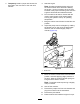
3.Loosentheboltsandangenutsinstalledinthe
levers(Figure83).
4.Aligntheleversinthefront-to-rearpositionby
bringingtheleverstogethertotheNEUTRAL
position,slidethemuntiltheyarealigned,and
tightenthebolts(Figure83).
g029726
Figure83
1.Bolt
3.Controllever
2.Handle4.Nut
g009195
Figure84
5.Iftheendsofthelevershitagainsteach
other,refertoAdjustingtheMotion-Control
Neutral-LockPivot(page62).
Adjustingthe
Motion-ControlLinkage
Thepump-controllinkagesarelocatedoneither
sideofthefueltank,belowtheseat.Rotatethe
pumplinkagewitha1/2inchwrenchforne-tuning
adjustmentssothatthemachinedoesnotmovein
neutral.Makeanyadjustmentsforneutralpositioning
only.
WARNING
Theenginemustberunningandthedrive
wheelsmustbeturning,sothemotion-control
adjustmentcanbeperformed.Contactwith
movingpartsorhotsurfacesmaycause
personalinjury.
Keepyourngers,hands,andclothingclear
ofrotatingcomponentsandhotsurfaces.
1.Priortostartingtheengine,pushthedeck-lift
pedal,removetheheight-of-cutpin,andlower
thedecktotheground.
2.Raisetherearofmachineandsupportitwith
jackstands(orequivalentsupport)justhigh
enoughtoallowthedrivewheelstoturnfreely.
3.Removetheelectricalconnectionfromtheseat
safetyswitch,locatedunderthebottomcushion
oftheseat.
Note:Theswitchisapartoftheseatassembly.
59