
Operator's Manual
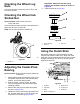
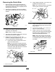

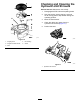


Table Of Contents
- NO TITLE
- NO TITLE
- NO TITLE
- Adding Fuel
- Checking the Engine-Oil Level
- Breaking in a New Machine
- Using the Rollover Protection System (ROPS)
- Entering the User Position
- Think Safety First
- Operating the Parking Brake
- Operating the Mower Blade-Control Switch (PTO)
- Operating the Throttle
- Operating the Choke
- Operating the Ignition Switch
- Using the Fuel Shutoff Valve
- Starting and Stopping the Engine
- Using the Safety-Interlock System
- Driving Forward or Backward
- Stopping the Machine
- Adjusting the Height-of-Cut
- Adjusting the Anti-Scalp Rollers
- Adjusting the Flow Baffle Cam Locks
- Positioning the Flow Baffle
- Positioning the Seat
- Unlatching the Seat
- Adjusting the MyRide™ Suspension System
- Using the Drive-Wheel-Release Valves
- Using the Side Discharge
- Transporting the Machine
- Loading the Machine
- NO TITLE
- NO TITLE
- NO TITLE
- NO TITLE
- NO TITLE

7.Removethebeltfromthehydraulicunitdrive
pulleysandtheenginepulley.
8.Installthenewbeltaroundenginepulleyand
the2drivepulleys.
9.Usingaratchetinthesquareholeintheidler
arm,installtheidlerspringtotheframe(Figure
82).
10.Installthemowerbelt;refertoReplacingthe
MowerBelt(page56).
ControlsSystem
Maintenance
Adjustingthe
Control-HandlePosition
Thereare2heightpositionsforthecontrol
levers—highandlow.Removetheboltstoadjustthe
heightfortheoperator.
1.DisengagethePTO,movethemotion-control
leverstotheneutral-lockedposition,andsetthe
parkingbrake.
2.Stoptheengine,removethekey,andwait
forallmovingpartstostopbeforeleavingthe
operatingposition.
3.Loosentheboltsandangenutsinstalledinthe
levers(Figure83).
4.Aligntheleversinthefront-to-rearposition
bybringingtheleverstogethertotheneutral
position,andslidethemuntiltheyarealigned,
thentightenthebolts(Figure84).
g029726
Figure83
1.Bolt
3.Controllever
2.Handle4.Nut
58