
Operator's Manual


CheckingforBentBlades
1.Disengagetheblade-controlswitch(PTO),move
themotion-controlleverstotheNEUTRAL-LOCK
position,andsettheparkingbrake.
2.Shutofftheengine,removethekey,andwait
forallmovingpartstostopbeforeleavingthe
operatingposition.
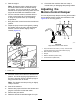
3.Rotatethebladesuntiltheendsfaceforward
andbackward(Figure99).
4.Measurefromalevelsurfacetothecutting
edge,positionA,oftheblades(Figure99).
g000975
Figure99
1.Measureherefromblade
tohardsurface
2.PositionA
5.Rotatetheoppositeendsofthebladesforward.
6.Measurefromalevelsurfacetothecuttingedge
ofthebladesatthesamepositionasinstep4.
Note:Thedifferencebetweenthedimensions
obtainedinsteps4and5mustnotexceed3mm
(1/8inch).
Note:Ifthisdimensionexceeds3mm
(1/8inch),thebladeisbentandmustbe
replaced.
WARNING
Abladethatisbentordamagedcould
breakapartandcouldseriouslyinjureor
killyouorbystanders.
•Alwaysreplacebentordamaged
bladewithanewblade.
•Donotleorcreatesharpnotchesin
theedgesorsurfacesoftheblade.
RemovingtheBlades
Replaceabladeifithitsanobject,ifthebladeisout
ofbalance,orifthebladeisbent.T oensureoptimum
performanceandcontinuedsafetyconformanceof
themachine,usegenuineT ororeplacementblades.
Replacementbladesmadebyothermanufacturers
mayresultinnonconformancewithsafetystandards.
1.Holdthebladeendusingaragorathickly
paddedglove.
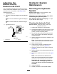
2.Removethebladebolt,curvedwasher,and
bladefromthespindleshaft(Figure100).
g004536
Figure100
1.Sailareaoftheblade3.Curvedwasher
2.Blade4.Bladebolt
67