
Service Manual


HYDRAULIC SYSTEM
5-33Toro Z Master G3 3000/5000/6000 Series Service Manual
5
a. Torque the slotted nut to 200 ft-lbs. (271 Nm).
b. Check distance from bottom of slot in nut to inside
edge of hole. Two threads (0.1” / 0.0cm) or less
should be showing.
c. If more than two threads (0.1” / 0.254cm) are
showing, remove nut and install washer between
hub and nut.
d. Torque the slotted nut to 200 ft-lbs. (271 Nm).
e. Then tighten nut until the next set of slots line up
with cross-hole in shaft. Do not loosen nut to align
the slot. If required, tighten to the next set of slots.
f. Install a new cotter pin.
Note: Do not use anti-seize on wheel hub.
24. Install the rear tires and torque the lug nuts to 103.5
– 126.5 ft-lbs. (140.5 – 171.5 Nm).
25. Install the negative battery cable to the battery.
26. Start the unit up and allow the unit to warm up for
about 5 minutes, moving the motion control levers
from forward to reverse. Bring the motion control
levers into the neutral position. The rear tires should
not move forward or reverse. If they do creep, see
“Adjusting the Motion Control Linkage (Neutral
Adjustment)” on page 5-34.
27. Remove the jack stands and lower the unit down.
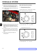
Fig. 372 g. 83 G009039
23. Using a 1/2” drive breaker bar installed in the square
hole in the pump idler assembly, rotate the idler arm
counter-clockwise to relieve tension and install the
v-belt around the engine pulley, UHT transmission
pulleys and the idler pulley (Fig. 372).
A. Idler pulley E. LH hydraulic pump
B. Clutch pulley pulley
C. Pump drive belt F. Square hole in idler arm
D. RH hydraulic pump G. Idler spring
pulley
A
B
C
D
E
F
G