
Operator's Manual


ProductOverview
g029631
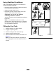
Figure4
1.Side-dischargedeector
8.Rear-shockassembly
(machineswithMyRide™
only)
2.Height-of-cutdecklift
pedal
9.Seatbelt
3.Parking-brakelever10.Fuelcap
4.Transportlock11.Mowerdeck
5.Controls12.Casterwheel
6.Motion-controllevers13.Front-shockassembly
(machineswithMyRide™
only)
7.Rollbar
Controls
Becomefamiliarwithallthecontrolsbeforeyoustart
theengineandoperatethemachine(Figure4and
Figure5).
ControlPanel
g008951
Figure5
1.Blade-controlswitch
(powertakeoff)
4.Hour
meter/Safety-interlock
display
2.Chokecontrol
5.Keyswitch
3.Throttlecontrol6.Fuses
HourMeter
Thehourmeterrecordsthenumberofhoursthe
enginehasoperated.Itoperateswhentheengine
isrunning.Usethesetimesforschedulingregular
maintenance(Figure6).
FuelGauge
Thefuelgaugeislocatedwithinthehourmeter,and
thebarslightupwhenthekeyswitchisintheON
position(Figure6).
Theindicatorlightappearswhenthefuellevelislow
(approximately1gallonremaininginthefueltank).
Safety-InterlockIndicators
Therearesymbolsonthehourmeterthatindicate
withablacktrianglethattheinterlockcomponentis
positionedcorrectly(Figure6).
Battery-IndicatorLight
IfyouturnthekeyswitchtotheONpositionfora
fewseconds,thebatteryvoltagedisplaysinthearea
wherethehoursarenormallydisplayed.
13