
Operator's Manual


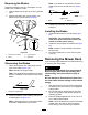


Table Of Contents
- NO TITLE
- NO TITLE
- NO TITLE
- NO TITLE
- During Operation Safety
- Entering the Operator’s Position
- Operating the Parking Brake
- Operating the Mower Blade-Control Switch (PTO)
- Operating the Throttle
- Operating the Choke
- Starting the Engine
- Shutting Off the Engine
- Using the Motion-Control Levers
- Driving the Machine
- Using the Side Discharge
- Adjusting the Height of Cut
- Adjusting the Anti-Scalp Rollers
- Adjusting the Flow Baffle Cam Locks
- Positioning the Flow Baffle
- NO TITLE
- NO TITLE
- NO TITLE
- NO TITLE
- NO TITLE
- NO TITLE
- What is this warning?
- What is Prop 65?
- Does this law apply everywhere?
- How do the California warnings compare to federal limits?
- Why don’t all similar products carry the warning?
- Why does Toro include this warning?
RemovingtheBlades
Replacethebladesiftheyhitasolidobject,orifthe
bladeisoutofbalanceorbent.
1.Holdthebladeendusingaragorthicklypadded
glove.
2.Removethebladebolt,curvedwasher,and
bladefromthespindleshaft(Figure99).
g004536
Figure99
1.Sailareaoftheblade3.Curvedwasher
2.Blade4.Bladebolt
SharpeningtheBlades
1.Usealetosharpenthecuttingedgeatboth
endsoftheblade(Figure100).
Note:Maintaintheoriginalangle.
Note:Thebladeretainsitsbalanceifthesame
amountofmaterialisremovedfrombothcutting
edges.
g000552
Figure100
1.Sharpenatoriginalangle.
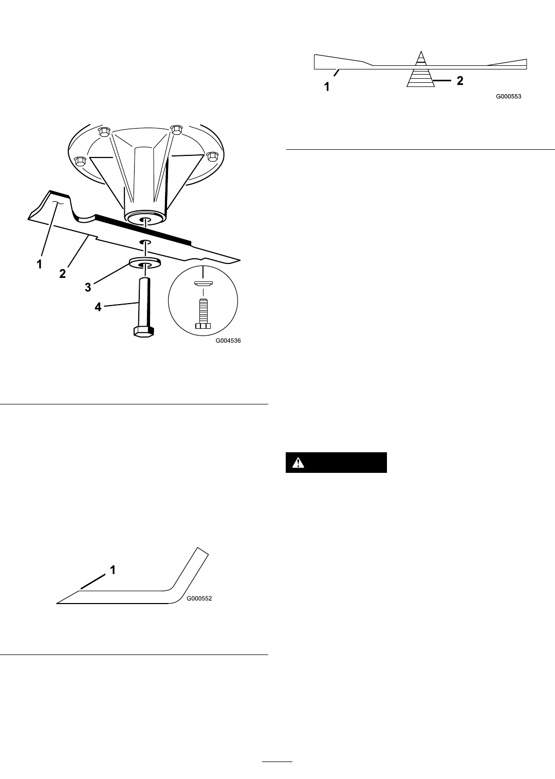
2.Checkthebalanceofthebladebyputtingiton
abladebalancer(Figure101).
Note:Ifthebladestaysinahorizontalposition,
thebladeisbalancedandcanbeused.
Note:Ifthebladeisnotbalanced,lesome
metalofftheendofthesailareaonly(Figure
100).
g000553
Figure101
1.Blade2.Balancer
3.Repeatthisprocedureuntilthebladeis
balanced.
InstallingtheBlades
1.Installthebladeontothespindleshaft(Figure
99).
Important:Thecurvedpartoftheblade
mustpointupwardtowardtheinsideofthe
mowertoensurepropercutting.
2.Installthecurvedwasherandbladebolt(Figure
99).
Note:Installthecurved-washerconetoward
thebolthead.
3.Torquethebladeboltto115to150N∙m(85to
110ft-lb).
RemovingtheMowerDeck
Lockoutthespring-loadeddeckarmsbeforeservicing
orremovingthemowerdeck.
WARNING
Deck-liftarmassemblieshavestoredenergy.
Removingthedeckwithoutreleasingthe
storedenergycancauseseriousinjuryor
death.
Donotattempttodisassemblethedeckfrom
thefrontframewithoutlockingoutthestored
energy.
1.Parkthemachineonalevelsurface,disengage
theblade-controlswitch(PTO),andengagethe
parkingbrake.
2.Shutofftheengine,removethekey,andwait
forallmovingpartstostopbeforeleavingthe
operatingposition.
3.Placetheheightadjustmentpininthe7.6cm(3
inch)cutting-heightlocation.
Note:Thislocksthedeck-liftarmsinthelowest
positionwhenthedeckisremovedandthe
storedenergyinthedeckspringisreleased.
65