
Service Manual


HYDRAULIC SYSTEM
5-24 Toro Z Master G3 3000/5000/6000 Series Service Manual
5
8. On the side of the machine being serviced, remove
the bolt and washer securing the hydro drive control
shaft (Fig. 340).
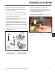
Fig. 338 DSCN-4504a
7. With the tension removed from the belt, remove the
v-belt from around the left side transmission pulley
(Fig. 339).
Fig. 339 DSCN-4508a
Fig. 340 DSCN-4510a
9. Pry the control arm off the square tapered shaft (Fig.
341).
Note: Be careful to not damage the trunnion shaft
seal.
Fig. 341 DSCN-4515a
6. Using a 1/2” drive breaker bar installed in the square
hole in the pump idler assembly, rotate the pump
idler arm counter-clockwise to relieve tension on the
v-belt (Fig. 338).