
Operator's Manual


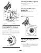


Figure56
1.PositiveBatteryPost
3.Red(+)ChargerLead
2.NegativeBatteryPost
4.Black(-)ChargerLead
ServicingtheFuses
Theelectricalsystemisprotectedbyfuses.Itrequires
nomaintenance,however,ifafuseblowscheckthe
component/circuitforamalfunctionorshort.
1.Thefusesarelocatedonrighthandconsolenextto
theseat(Figure57).
2.Toreplacethefuses,pulloutonthefusetoremoveit.
3.Installanewfuse(
Figure57).
Figure57
1.Optionalaccesory-15amp
4.Main-25amp
2.Charge-25amp5.Console
3.PTO-10amp
JumpStartingtheMachine
1.Checkandcleancorrosionfromthebatteryterminals
beforejumpstarting.Ensuretheconnectionsaretight.
CAUTION
Corrosionorlooseconnectionscancause
unwantedelectricalvoltagespikesatanytime
duringthejumpstartingprocedure.
DoNotattempttojumpstartwithlooseor
corrodedbatteryterminalsordamagetothe
engineorEFImayoccur.
DANGER
Jumpstartingaweakbatterythatiscracked,
frozen,haslowelectrolytelevel,oran
open/shortedbatterycell,cancausean
explosionresultinginseriouspersonalinjury.
DoNotjumpstartaweakbatteryifthese
conditionsexist.
41