
Operator's Manual


ProductOverview
G021417
7
6
5
4
3
2
1
8
9
10
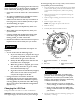
Figure4
1.Height-of-cutdecklift
pedal
6.Fueltank
2.Transportlock7.Rollbar
3.Parkingbrakelever8.Motioncontrollevers
4.Controls9.Casterwheel
5.Seatbelt
10.Mowerdeck
Controls
Becomefamiliarwithallthecontrolsbeforeyoustartthe
engineandoperatethemachine(Figure4andFigure5).
g0131 12
1
2
3
4
5
6
25
25
10
15
C
H
ECK
ENG
IN
E
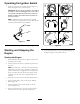
Figure5
1.PTOSwitch4.Hourmeter/Safety
interlockdisplay
2.Throttlecontrol5.Ignitionswitch
3.Malfunctionindicatorlight
(MIL)
6.Fuses
HourMeter
Thehourmeterrecordsthenumberofhourstheenginehas
operated.Itoperateswhentheengineisrunning.Usethese
timesforschedulingregularmaintenance(Figure6).
FuelGauge
LocatedontheLPGfueltank.
ThisgaugemonitorstheamountofliquidLPGinthefuel
tank.
SafetyPressureReliefValve
ThereliefvalveislocatedontheLPGfueltank(Figure7).
Thesafetypressurereliefvalverelievestheexcesspressure
intheLPGtank.
Important:Thisvalvehasaprotectiveplasticcap
thatshouldneverberemoved.Ifthecapisdamaged
ormissing,contacttrainedandqualiedpersonnel
immediately.
LPGCylinderBrackets
Thebracketsarelocatedontheenginedeck.
TheLPGcylinderbracketsareusedtofastentheremovable
LPGtanktothemower.
SafetyInterlockIndicators
Therearesymbolsonthehourmeterandtheindicatewitha
blacktrianglethattheinterlockcomponentisinthecorrect
position(Figure6).
12