
Operator's Manual

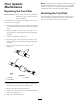

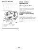


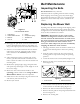

Figure69
1.Hydraulicunitshrouds
6.Overeachdipstick,removethecoverandthebolt
attachedtothecover.Cleanaroundeachdipstick
andhydraulicunit(
Figure70).
7.Installthecoverovereachdipstick.
8.Adjusttheseat.
G012434
1
2
Figure70
1.Cover
2.Bolt
BrakeMaintenance
AdjustingtheParkingBrake
ServiceInterval:Aftertherst100hours
Every500hoursthereafter
Checktomakesurebrakeisadjustedproperly.This
proceduremustbefollowedaftertherst100hoursor
whenabrakecomponenthasbeenremovedorreplaced.
1.Drivethemachineontoalevelsurface.
2.Disengagethebladecontrolswitch(PTO),movethe
motioncontrolleverstotheneutrallockedposition
andsettheparkingbrake.
3.Stoptheengine,waitforallmovingpartstostop,
andremovethekey.
4.Raisethebackofthemachineupandsupportthe
machinewithjackstands.
DANGER
Mechanicalorhydraulicjacksmayfailto
supportmachineandcauseaseriousinjury.
•Usejackstandwhensupportingmachine.
•Donotusehydraulicjacks.
5.Removethereartiresfromthemachine.
6.Removeanydebrisfromthebrakearea.
7.Rotatethedrivewheelreleasehandletothereleased
position.RefertotheUsingtheDriveWheel
ReleaseValvessectioninOperation.
8.Measuretheoveralllengthofthecompression
spring.Thecorrectlengthshouldbebetween1-1/2
and1-9/16inches(3.8and4.0cm).Ifthespring
lengthiswithinthisrange,noadjustmentisneeded.
Ifitisnot,proceedtostep
9.
9.Holdthethreadedrodendwithatoolandadjust
thelocknutuntilthespringlengthisbetween1-1/2
and1-9/16inches(3.8and4.0cm)(
Figure71).Do
Notallowthecabletoturnwhenthenutsarebeing
loosened.
49