
Operator's Manual


1
3
2
G017027
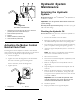
Figure88
1.Deckliftpedal
3.Transportlock
2.Heightofcutpin
6.Inserttheheightadjustmentpinintothe3inch(7.6
cm)cuttingheightlocation.
7.Releasethetransportlockandallowthedecktolower
tothecuttingheight.
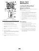
8.Raisethedischargechute.
9.Onbothsidesofthedeck,measurefromthelevel
surfacetothefronttipoftheblade(PostionA).
Themeasurementshouldread3inches(7.6mm)
(Figure89).
Figure89
1.3inches(7.6cm)atAis
correct
3.Measureherefromthe
bladetiptohardsurface
2.31/4inches(8.3cm)atB
iscorrect
4.MeasureatAandBon
bothsides
10.Fine-tunetheadjustmentnutonthefrontdecklift
assemblybyturningit(Figure90).
Toincreasetheheight,turntheadjustmentnut
clockwise;todecrease,turncounterclockwise.
G012430
1
2
2 1
3 4
Figure90
1.Adjustmentnut3.Reardeckadjustment
2.JamNut4.Frontdeckadjustment
11.Ifthefrontdecklinksdonothaveenoughadjustment
toachieveaccuratecutheight,thesinglepoint
adjustmentcanbeutilizedtogainmoreadjustment.
12.Toadjustthesinglepointsystem,loosenthetwobolts
atthebottomoftheheightofcutplate.Referto
Figure91.
55