
Operator's Manual


2.Shutofftheengine,removethekey,andwait
forallmovingpartstostopbeforeleavingthe
operatingposition.
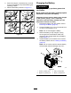
3.Usinganaircompressor,blowoutanydebris
fromunderthebrakepoleandaroundthebrake
spacers(Figure81).
g010868
Figure81
4.Checktheconditionofthewire-harnessleads,
connectors,andterminals.
Note:Cleanorrepairasnecessary.
5.Verifythat12Vispresentattheclutchconnector
whentheblade-controlswitch(PTO)switchis
engaged.
6.Measurethegapbetweentherotorand
armature.Ifthegapisgreaterthan1mm(0.04
inch),dothefollowingsteps:
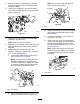
A.Loosenbothbrake-mountingbolts1/2to1
fullturnasshowninFigure82.
Note:Donotremovethebrakepolefrom
theeldshell/armature.Thebrakepole
hasworntomatchthearmatureandneeds
tocontinuetomatchafteryouremovethe
shimtoensureproperbraketorque.
g010870
Figure82
1.Brake-mountingbolt
B.Usingneedle-nosepliers,orbyhand,hold
thetabandremovetheshim(Figure83).
Note:Donotdiscardtheshimuntilthe
clutchisfunctioningproperly.
g010871
Figure83
1.Shim
C.Usingapneumaticline,blowoutanydebris
fromunderthebrakepoleandaroundthe
brakespacers.
D.Torqueeachbolt(M6x1)to12.3to13.7
N∙m(9.5to10.5ft-lb).
E.Usinga0.25mm(0.01inch)thickfeeler
gauge,verifythatagapispresentbetween
therotorandthearmaturefaceonboth
sidesofthebrakepoleasshowninFigure
84andFigure85.
Note:Duetothewaytherotorandthe
armaturefaceswear(peaksandvalleys)it
issometimesdifculttomeasurethegap
accurately.
g010872
Figure84
1.Feelergauge
57