
Operator's Manual


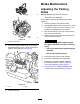


g010868
Figure71
4.Checktheconditionofthewire-harnessleads,
connectors,andterminals.Cleanorrepairthem
asnecessary.
5.Verifythat12Vispresentattheclutchconnector
whentheyouengagetheblade-controlswitch
(PTO).
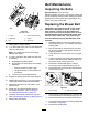
6.Measurethegapbetweentherotorand
armature.Ifthegapisgreaterthan1mm(0.04
inch),proceedwiththefollowingsteps:
A.Loosenbothbrakemountingbolts1/2to1
fullturnasshowninFigure72.
Note:Donotremovethebrakepolefrom
theeldshell/armature.Thebrakepole
hasworntomatchthearmatureandneeds
tocontinuetomatchafteryouremovethe
shimtoensuretheproperbraketorque.
g010870
Figure72
1.Brake-mountingbolt
B.Usingneedle-nosepliers,orbyhand,
removetheshim.
Note:Donotdiscardtheshimuntilyou
conrmthattheclutchfunctionsproperly.
g010871
Figure73
1.Shim
C.Usingapneumaticline,blowoutanydebris
underthebrakepoleandaroundthebrake
spacers.
D.Torqueeachbolt(M6x1)to12.3to13.7
N∙m(9.5to10.5ft-lb).
53