
Operator's Manual


G012806
1
2
3
4
3
2
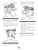
Figure33
1.Bafeguard3.Carriagebolt(5/16x3/4
inch)
2.Locknut(5/16inch)4.Rightbafe
10.Locatethebafeguardatthefrontedgeoftheside
dischargeopening.Removethefastenerssecuring
thebafeguardandtherightbafetothemower
deckasshowninFigure33.Removethebafe
guardandretainallfasteners.
11.Removethetwolocknuts(5/16inch)tosecuring
theweldedpostsoftherightbafetothetop
ofthemowerdeckatcenterandrightofcenter
positions(
Figure34).Removetherightbafefrom
themowerdeck.
1
2
3
G012805
Figure34
1.Locknut(5/16inch)3.Weldedposts,rightbafe
2.Rightbafe
12.Installthefastenersremovedpreviouslyatthefront
holesinthedischargeplateandforwardholeinthe
deck(Figure33).
13.Locatethecutoffbafeintheloosepartsbag.
Removethefastenersattherearholesofthe
dischargeplate.Installthebafeattheside
dischargeopeningonthemowerdeck(
Figure35).
G012800
1
2
3
4
Figure35
1.Carriagebolt,existing3.Cutoffbafe,shipped
loose
2.Rearholesinthe
dischargeplate
4.Locknut,existing
14.Usethefastenersremovedtosecurethecutoff
bafetothedeck.
15.Installthebladestothedeck.RefertotheInstalling
theBladesprocedureintheMaintenancesectionfor
moreinformation.
Note:Standardcuttingbladeswillimprove
dischargeperformanceandcanobtainedfromyour
localauthorizedTorodealer.
16.InstallthemowerasdescribedintheInstallingthe
MowerprocedureintheMaintenancesectionfor
moreinformation.
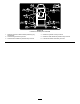
UsingtheSideDischarge
Themowerhasahingedgrassdeectorthatdisperses
clippingstothesideanddowntowardtheturf.
26