
Operator's Manual


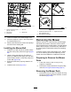


3.Measurefromthetipofthebladetotheat
surfacehere.
g014973
Figure55
1.Blade,inpositionformeasuring
2.Levelsurface
3.Measureddistancebetweenbladeandsurface(A)
4.Rotatethesameblade180degreessothat
theopposingcuttingedgeisnowinthesame
position.
g014974
Figure56
1.Blade,sidepreviouslymeasured
2.Measurementpositionusedpreviously
3.Opposingsideofbladebeingmovedintomeasurement
position
5.Measurefromthetipofthebladetotheat
surfacehere.Thevarianceshouldbenomore
than3mm(1/8inch).
g014973
Figure57
1.Opposingbladeedge,inpositionformeasuring
2.Levelsurface
3.Secondmeasureddistancebetweenbladeandsurface(B)
WARNING
Abladethatisbentordamagedcould
breakapartandcouldseriouslyinjureor
killyouorbystanders.
•Alwaysreplaceabentordamaged
bladewithanewblade.
•Neverleorcreatesharpnotchesin
theedgesorsurfacesoftheblade.
A.IfthedifferencebetweenAandBisgreater
than3mm(1/8inch)replacethebladewith
anewblade.RefertoRemovingtheBlades
(page44)andInstallingtheBlades(page
45).
Note:Ifabentbladeisreplacedwithanew
oneandthedimensionobtainedcontinues
toexceed3mm(1/8inch),thebladespindle
couldbebent.ContactanAuthorizedT oro
Dealerforservice.
B.Ifthevarianceiswithinconstraints,moveto
thenextblade..
6.Repeatthisprocedureoneachblade.
RemovingtheBlades
Bladesmustbereplacedifasolidobjectishit,ifthe
bladeisoutofbalanceorisbent.T oensureoptimum
performanceandcontinuedsafetyconformanceof
themachine,usegenuineT ororeplacementblades.
Replacementbladesmadebyothermanufacturers
mayresultinnon-conformancewithsafetystandards.
Holdthebladeendusingaragorthickly-paddedglove.
Removethebladebolt(rotatingitcounter-clockwise),
curvedwasher,andbladefromthespindleshaft
(Figure58).
44