
Operator's Manual


3.Removethedamagedorworndischarge
deector.
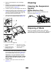
4.Positionthenewdischargedeectorwiththe
bracketendsbetweentheweldedbracketson
thedeckasshowninFigure78.
5.Installthespringontothestraightendoftherod.
6.PositionthespringontherodasshowninFigure
78sothattheshorterspringendcomesfrom
undertherodbeforethebendandgoingover
therodasitreturnsfromthebend.
7.Lifttheloopendofthespringandplaceitinto
thenotchonthedeectorbracket(Figure78).
g297573
Figure78
1.Rodandspringassembly
installed
3.Rod,shortend,moved
behindthemowerbracket
2.Loopendofthespring
installedintothenotchin
thedeectorbracket
4.Shortend,retainedby
mowerbracket.
8.Securetherodandspringassemblybytwisting
itsothattheshortendoftherodisbehindthe
frontbracketweldedtothedeck(Figure78).
Important:Thegrassdeectormustbe
springloadedinthedownposition.Liftthe
deectoruptotestthatitsnapstothefull
downposition.
9.Installthecotterpinintotheendoftherod
(Figure77).
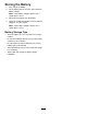
Cleaning
CleaningtheSuspension
System
MyRideMachinesOnly
Note:Donotcleantheshockassemblieswith
pressurizedwater(Figure79).
g030538
Figure79
DisposingofWaste
Engineoil,batteries,hydraulicuid,andengine
coolantarepollutantstotheenvironment.Disposeof
theseaccordingtoyourstateandlocalregulations.
51