
Operator's Manual


ConvertingtoSide
Discharge
Themowerdeckandmowerbladesshippedwiththe
machineweredesignedforoptimummulchingand
side-dischargeperformance.
Installthefastenersintothesameholesinthedeck
fromwheretheywereoriginallyremoved.This
ensuresthatnoholesareleftopenwhenoperating
themowerdeck.
WARNING
Openholesinthemachineexposeyouand
otherstothrowndebristhatcancausesevere
injury.
•Neveroperatethemachinewithout
hardwaremountedinallholesinthe
machinehousing.
•Installthehardwareinthemountingholes
whenyouremovethemulchingbafe.
Machineswith122cm(48-inch)
MowerDecks
1.Parkthemachineonalevelsurface,disengage
theblade-controlswitch,andengagetheparking
brake.
2.Shutofftheengine,removethekey,andwait
forallmovingpartstostopbeforeleavingthe
operatingposition.
3.Removethemowerdeck;refertoRemovingthe
MowerDeck(page46).
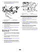
4.Removethe2locknuts(5/16inch)securedto
theweldedpostsoftheleftbafeonthetopof
themowerdeckatthecenterandleftofcenter
positions(Figure28).
g011149
Figure28
1.Locknut(5/16inch)3.Leftbafe
2.Carriagebolt(5/16x3/4
inch)
4.Installthefastenershere.
5.Removethecarriageboltandlocknutonthe
sidewallofthemowerdecksecuringtheleft
bafetothedeck.
6.Removetheleftbafefromthemowerdeckas
showninFigure28.
7.Removethe2carriagebolts(5/16x3/4
inch)and2locknuts(5/16inch)securingthe
assembledrightbafeandbafeguardtothe
mowerdeck(Figure29).
g191136
Figure29
1.Carriagebolt(5/16x3/4
inch)
3.Rightbafe
2.Locknut(5/16inch)4.Bafeguard
8.Removethe2locknuts(5/16inch)tosecuring
theweldedpostsoftherightbafetothetopof
themowerdeckatthecenterandrightofcenter
positions(Figure30).
Note:Removetherightbafefromthemower
deck.
g010704
Figure30
1.Locknut(5/16inch)3.Weldedposts(rightbafe)
2.Rightbafe
23