
Setup Instructions


Page 3
IMPORTANT: Make sure the negative battery
cables are disconnected and the battery charger
used for charging the battery has an output of 16
volts and 7 amps or less to avoid damaging the
battery (see chart below for recommended charger
settings).
Voltage
Reading
Percent
Charge
Maximum
Charger
Settings
Charging
Interval
12.6 or greater 100%
16 volts /
7 amps
No Charging
Required
12.4 – 12.6 75 – 100%
16 volts /
7 amps
30 Minutes
12.2 – 12.4 50 – 75%
16 volts /
7 amps
1 Hour
12.0 – 12.2 25 – 50%
14.4 volts /
4 amps
2 Hours
11.7 – 12.0 0 – 25%
14.4 volts /
4 amps
3 Hours
11.7 or less 0%
14.4 volts /
2 amps
6 Hours
or More
CAUTION
POTENTIAL HAZARD
♦ If the ignition is in the “ON” position there is
potential for sparks and engagement of
components.
WHAT CAN HAPPEN
♦ Sparks could cause an explosion or moving
parts could accidentally engage causing
personal injury.
HOW TO AVOID THE HAZARD
♦ Be sure ignition switch is in the “OFF” position
before charging the battery.
3. Connect the negative battery cables.
NOTE: If the positive cable is also disconnected,
connect the positive (red) cable to the positive
battery terminal first, then the negative (black)
cable to the negative battery terminal. Slip
insulator boot over the positive terminal.
NOTE: If time does not permit charging the
battery, or if charging equipment is not available,
connect the negative battery cables and run the
vehicle continuously for 20 to 30 minutes to
sufficiently charge the battery
.
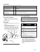
Installing the Motion Control Levers
1. Remove the bottom 3/8” x 1” bolt and spring disc
washer from the control arm shaft. Loosen the
upper 3/8” x 1” bolt and spring disc washer in the
control lever so that the lever can rotate (See
Figure 2).
2. Position the lever so the bottom hole aligns with
hole in the control arm shaft. Install spring disc
washer and bolt.
3. Repeat on opposite side of unit.
NOTE: There are two lever height options
available. Place the levers in the top two holes
to increase height of the levers, or in the bottom
two holes to decrease the height of the levers.
Figure 2
1. Bolt 4. Control Arm Shaft
2. Spring Disc Washer 5. Seat
3. Motion Control Lever
4. Align the levers front/rear position. With the
levers in the neutral position, loosen the
hardware and adjust the levers sliding and/or
tilting the lever(s) forward or backward until
properly aligned and tighten hardware
(Figure. 3).
Figure 3
1. Hardware
2. Motion Control Lever