
Service Manual


310-2400/2600 IZT 19
BRAKES
(Cog Brake)
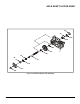
Refer to Figure 9.
DISASSEMBLY
1. Remove the external retaining ring (63).
2. Remove the brake bolt (123), brake arm
(70) and brake disc (73). Note the orienta-
tion of the hub on the brake disc.
INSPECTION
1. Inspect the brake disc (73) for damaged
splines or gear teeth.
2. Inspect the brake arm (70) for damaged
teeth.
ASSEMBLY
1. Insert the brake shaft (55) into the main
housing (1). Slide the brake disc (73) onto
the brake shaft (55). Note the orientation of
the brake disc. The hub on the brake disc
should face inward on R.H. units and out-
ward on L.H. units.
2. Install the brake arm (70) and brake bolt
(123) onto the main housing (1). Tighten the
brake bolt (123) to the torque value listed in
Table 5.
3. Install an external retaining ring (63) onto
the brake shaft (55).
73
63
70
1
123
55
Figure 9. Cog Brake Assembly