
Operator's Manual


G014930
1
2
3
3
4
5
1
2
3
3
4
5
6
4
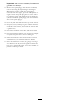
Figure61
MowerDeckswith2Blades
1.Idlerpulley
4.Spring
2.Mowerbelt5.Enginepulley
3.Outsidepulley6.Springremovaltoo
G014931
1
2
3
3
4
5
6
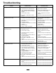
Figure62
MowerDeckswith3Blades
1.Idlerpulley
4.Spring
2.Mowerbelt5.Enginepulley
3.Outsidepulley6.Springremovaltoo
5.Routethenewbeltaroundtheenginepulleyand
mowerpulleys(Figure62).
6.Usingaspringremovaltool,(Toropartno.92-5771),
installtheidlerspringoverthedeckhookand
placingtensionontheidlerpulleyandmowerbelt
((Figure61andFigure62)).
InstallingtheMower
1.Parkthemachineonalevelsurfaceanddisengage
thebladecontrolswitch.
2.Movethemotioncontrolleversoutwardtothe
parkposition,stoptheengine,removethekey,and
waitforallmovingpartstostopbeforeleavingthe
operatingposition.
3.Slidethemowerunderthemachine.
4.Lowertheheight-of-cutlevertothelowestposition.
5.Lifttherearofthemowerdeckandguidethehanger
bracketsovertherearliftrod(
Figure60).
6.Attachthefrontsupportrodtothemowerdeckwith
theclevispinandhairpincotter(Figure59).
7.Installthemowerbeltontotheenginepulley;refer
toReplacingtheMowerBelt.
ReplacingtheGrassDeector
ServiceInterval:Beforeeachuseordaily—Inspectthe
grassdeectorfordamage
WARNING
Anuncovereddischargeopeningcouldallowthe
lawnmowertothrowobjectsintheoperator’sor
bystander’sdirectionandresultinseriousinjury.
Also,contactwiththebladecouldoccur.
Neveroperatethemachinewithoutgrassdeector,
dischargecoverorgrasscollectionsysteminplace.
Inspectthegrassdeectorfordamagebeforeeachuse.
Replaceanydamagedpartsbeforeuse.
1.LocateitemsshowninFigure63.
44