
Service Manual


CHASSIS
3-13
Toro TimeCutter SS/MX/ZS Service Manual
3
Speed Control / Smart Speed Lever
Service
Speed Control / Smart Speed Lever
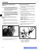
Removal
Note: The control box assembly does not need to
be removed from the frame to service the
smart speed components.
1. Remove (1) screw (A) that attaches the speed
control knob to the speed control lever (B).
2. Raise seat into service position.
3. Disconnect and remove battery from frame.
4. Remove the (4) screws (C) and (2) retaining plates
(D).
5. Maneuver the speed control lever (B) off of hydro
pins (F) and out of frame.
(Fig. 022)
Speed Control / Smart Speed Lever
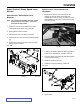
Installation
1. Maneuver the speed control lever (B) into the
chassis. Be sure the speed control lever rod
engages the control box notch (G) and the rod end
forks engage the hydro pin (F) on both the RH and
LH side (Fig. 023).
Fig. 022 PICT-1048
Fig. 023 PICT-1047
C
A
B
D
G
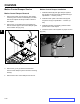
2. Install the (2) retaining plates (D) and torque the (4)
screws (C) to specication – 60 in-lbs. (6.5 Nm).
3. Cycle the speed control lever (B) into both positions
to verify smooth function.
4. Install the speed control knob.
5. Install and connect the battery. Lower seat.
(Fig. 024)
Fig. 024 PICT-1046
B
F
K
K. Nylon washer