
Service Manual


HYDROSTATIC DRIVE SYSTEM
5-11
Toro Timecutter SS/MX/ZS Service Manual
5
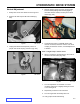
4. Torque fasteners in sequence to specication as
shown:
Wide Frame:
1st - Torque fastener (E) to specication – 17 ft-lbs.
(23 Nm) (Fig. 072)
2nd - Torque fastener (F) to specication – 17 ft-lbs.
(23 Nm) (Fig. 072)
Fig. 072 PICT-1106
3rd - Torque fastener (G) to specication – 17 ft-lbs.
(23 Nm) (Fig. 073)
Fig. 073 PICT-1099
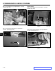
Transaxle Installation
1. Wide Frame Only – If a new hydro assembly is
being installed, transfer the (2) mounting brackets
(C and D) to the new hydro assembly and torque the
fasteners to specication; C - 30 ft-lbs. (40 Nm) and
D - 8 ft-lbs. (14 Nm) (Fig. 071).
Fig. 071 PICT-1105
2. Position the hydro assembly up into the unit frame
and align mounting points.
3. Loosely install all the hydro mounting fasteners and
center support fasteners. Do not fully tighten at this
time.
C
D
E
F
G