
Service Manual


ELECTRICAL
7-15
Toro TimeCutter SS/MX/ZS Service Manual
7
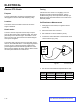
Measuring Clutch Current Draw
Note: Do not measure current draw if clutch
has shorted to ground or if the resistance
measurement is out of specication.
1. Disengage PTO switch, turn ignition off and remove
key.
2. Disconnect clutch wire connector.
3. Set the multimeter to check amps (10 amp scale).
4. Connect the positive meter lead to the chassis
harness terminal A (brown wire) (Fig. 171).
5. Connect the negative meter lead to the correspond-
ing wire terminal B (Fig. 171).
6. Connect a short jumper lead from terminal C to
terminal D (Fig. 171).
7. Turn the ignition key in the switch to “RUN” position
and the PTO switch to the “ON” position.
8. See the “PTO Clutch Electrical Specications” chart
below.
A
B
D
C
Fig. 171 clutch current msmt_v2
PTO Clutch Electrical Specications
PTO
Clutch
Ohms
Specication
Amp Draw
Specication
Continuity
to Ground
A
2.84 + 10% 4.23A + 10% OPEN
B
3.0 + 10% 3.97A + 10% OPEN
PTO Clutch Continuity to Ground Check
1. Disengage PTO switch, turn ignition off and remove
key.
2. Disconnect clutch wire connector.
3. Set multimeter to check resistance (ohms).
4. Connect one meter lead to the engine, chassis or
battery ground. Connect the other meter lead to
each of the PTO clutch terminals.
5. The two PTO terminals should never have continuity
to ground and should be OPEN at all times.
If continuity is found between the clutch wires
and ground, the clutch and PTO switch must be
replaced.
Clutch Style A (Fig. 169)
Fig. 169 PICT-1031a
Clutch Style B (Fig. 170)
Fig. 170 PICT-1031b