
Service Manual


MOWER DECK
6-31
Toro Timecutter SS/MX/ZS Service Manual
6
Fig. 136 g. 52 G005074
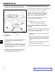
6. Move to the left side of the machine. Loosen, but
do not remove, the rear locking nut on the hanger
bracket (Fig. 136).
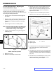
5. Carefully rotate the blades side-to-side (Fig. 135).
Measure between the outside cutting edges and the
level surface (Fig. 135). If both measurements are
not within 3/16” (5mm), an adjustment is required;
continue with this procedure.
Mower decks with (2) blades
A. Blades side-to-side D. Measure from blade tip
B. Sail area of blade to level surface
C. Outside cutting edges
A. Hanger bracket D. Eccentric adjustment plate
B. Rear locking nut E. Socket wrench hole
C. Side locking nut F. Socket wrench with 3/8”
extension
Fig. 135 g. 51 G009682
A
B
B
C
C
D D
A
B
C
D
E
F
7. Loosen the side locking nut on the hanger bracket
just enough to allow the eccentric plate to be
adjusted (Fig. 135). Use a 3/8” drive extension on a
socket wrench to manipulate the eccentric plate. Use
the wrench to reposition the deck height and adjust
so the measurements taken in Step 5 are within
3/16” (5mm).
8. When at the desired position, tighten the side locking
nut on the hanger bracket (Fig. 136). Tighten the
rear locking nut on the hanger bracket.
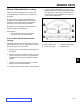
9. Continue leveling the deck by checking the front-
to-rear blade slope; refer to “Adjusting the Front-to-
Rear Blade Slope” in this chapter.