
Service Manual


MOWER DECK
6-27
Toro Timecutter SS/MX/ZS Service Manual
6
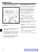
5. Measure between the outside cutting edges and
the level surface (Fig. 126 and Fig. 127). If both
measurements are not within 3/16” (5mm), an
adjustment is required; continue with this procedure.
6. Support deck by placing wood blocks under the
edges of the deck.
Note: Avoid placing the supports under any anti-
scalp rollers if present on the deck.
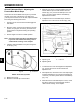
7. Move to the left side of the machine. Remove the
side carriage bolt (E) and locking nut (D) from the
xed position. Install it into the rear slotted position
and leave it slightly loose (Fig. 128).
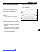
8. Loosen but do not remove, the rear locking nut on
the hanger bracket (Fig. 129).
A. Hanger bracket C. Fixed position
B. Slotted adjustment D. Side locking nut
position E. Side carriage bolt
Fig. 128 g. 49 G015323
A
B
C
D
E
A. Hanger bracket C. Side locking nut
B. Rear locking nut slotted position
D. Adjustment notches
Fig. 129 g. 50 G015324
A
B
C
D