
Operator's Manual


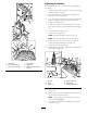


2.Removeonebushing,thenpullthespannerbushing
androllerbearingoutofthewheelhub(Figure60).
3.Removetheotherbushingfromthewheelhub,and
cleananygreaseanddirtfromthewheelhub(Figure
60).
4.Inspecttherollerbearing,bushings,spannerbushing
andtheinsideofthewheelhubforwear.
Note:Replaceanydefectiveorwornparts(Figure60).
5.Placeonebushingintothewheelhub(Figure60).
6.Greasetherollerbearingandspannerbushing,and
slidethemintothewheelhub(
Figure60).
7.Placethesecondbushingintothewheelhub(Figure
60).
8.Installthecasterwheelintothecasterforkandsecure
itwiththewheelboltandlocknut(Figure60).
9.Tightenthelocknutuntilthespannerbushingbottoms
againsttheinsideofthecasterforks(Figure60).
10.Greasethettingonthecasterwheel.
AdjustingtheElectricClutch
ServiceInterval:Every100hours—Checktheelectric
clutch.
Theclutchisadjustabletoensureproperengagementand
properbraking.
1.Inserta0.4to0.5mm(0.01to0.02inches)feelergauge
throughoneinspectionslotinthesideoftheassembly.
Note:Makesureitisbetweenthearmatureandthe
rotorfrictionsurfaces.
Note:Thegapneedstobeatleast0.4mm(0.02
inches)andnotmorethan0.5mm(0.02inches).
2.Ifadjustmentisneeded,usea0.4mm(0.02inches)
feelergaugetoseteachofthe3adjustment-slot
positions.
3.Tightenthelocknutsuntilthereisslightbindingon
thefeelergauge,butitcanbemovedeasilywithinthe
airgap(Figure61).
4.Repeatthisfortheremainingslots.
5.Checkeachslotagainandmakeslightadjustmentsuntil
thefeelergaugebetweentherotorandarmaturewith
veryslightcontactbetweenthem.
Figure61
1.Adjustingnut3.Feelergauge
2.Slot
43