
Operator's Manual
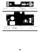


Controls
Becomefamiliarwithallthecontrols(Figure5)before
youstarttheengineandoperatethemachine.
g015230
3
4
5
6
7
8
9
10
11
12
13
Figure5
48inchand52inchmachines
1.Parkingbrakelever
8.Height-of-cutpin
2.Choke9.Platformlatch
3.Hourmeter10.Throttlecontrol
4.Ignitionswitch11.Rightmotioncontrollever
5.Fuelgauge
12.Bladecontrolswitch(PTO)
6.Height-of-cutlever13.Leftmotioncontrollever
7.Fuelcap
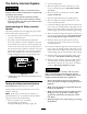
g015396
1 2 3 4 5 6
7
8
9
10
11
12
13
Figure6
60inchmachine
1.Parkingbrakelever8.Fuelcap
2.Choke9.Platformlatch
3.Hourmeter10.Throttlecontrol
4.Ignitionswitch11.Rightmotioncontrollever
5.Fuelgauge
12.Bladecontrolswitch(PTO)
6.Height-of-cutlever13.Leftmotioncontrollever
7.Height-of-cutpin
HourMeter
Thehourmeterrecordsthenumberofhourstheengine
hasoperated.Itoperateswhentheengineisrunning.
Usethesetimesforschedulingregularmaintenance
(Figure7).
FuelGauge
Thefuelgaugeislocatedonthetop,middleofthetank
(Figure5).
SafetyInterlockIndicators
Therearesymbolsonthehourmeterandindicatewith
ablacktrianglethattheinterlockcomponentisinthe
correctposition(Figure7).
BatteryIndicatorLight
IftheignitionkeyisturnedtotheOnpositionforafew
seconds,thebatteryvoltagewillbedisplayedinthearea
wherethehoursarenormallydisplayed.
Thebatterylightturnsonwhentheignitionisturned
onandwhenthechargeisbelowthecorrectoperating
level(Figure7).
13