
Operator's Manual


g010870
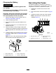
Figure60
1.Brake-mountingbolt
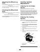
B.Usingneedle-nosepliers,orbyhand,
removetheshim.
Note:Donotdiscardtheshimuntilyou
conrmthattheclutchfunctionsproperly.
g010871
Figure61
1.Shim
C.Usingapneumaticline,blowoutanydebris
underthebrakepoleandaroundthebrake
spacers.
D.Torqueeachbolt(M6x1)to12.3to13.7
N∙m(9.5to10.5ft-lb).
E.Usinga0.010inchthick-feelergauge,verify
thatagapispresentbetweentherotorand
armaturefaceonbothsidesofthebrake
poleasshowninFigure62andFigure63.
Note:Duetothewaytherotorand
armaturefaceswear(peaksandvalleys),it
issometimesdifculttomeasurethetrue
gap.
g010872
Figure62
1.Feelergauge
g010873
Figure63
1.Feelergauge
•Ifthegapislessthan0.010inch,
theninstalltheshimandreferto
Troubleshooting(page62).
•Ifthegapissufcient,proceedtothe
safetycheckinstepF.
F.Performthefollowingsafetycheck:
i.Sitontheseatandstarttheengine.
ii.Makesurethatthebladesdonot
engagewhentheblade-control
switch(PTO)isintheOFFposition
andtheclutchisdisengaged.
Note:Iftheclutchdoesnot
disengage,installtheshim,andrefer
toTroubleshooting(page62).
iii.Engageanddisengagethe
blade-controlswitch(PTO)10
consecutivetimestoensurethatthe
clutchisfunctioningproperly.
Note:Iftheclutchdoesnotengage
properly,refertoTroubleshooting
(page62).
45