
Operator's Manual


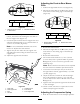


Figure52
1.Ratchetwithshort
extensionorbreaker
bar
2.Squarehole
8.Toincreasethebelttension,rotatetheratchetor
breakerbarcounterclockwisetomovethexed
idlerarmuntilyoufeelincreasedresistanceandthe
spring-loadedidlerpulleystopsmoving.
Note:Donotincreasethebelttensionbeyondthe
pointwherethexedidlerarmstops.
9.Whileholdingthebeltintension,tightenthe2bolts
thatsecurethexedidlerarm.
10.Removetheratchetorbreakerbarfromthesquare
holeinthexedidlerarm.
11.Installthebeltcoversovertheoutsidespindles.
ReplacingthePumpDriveBelt
1.Removethemowerbeltrst;refertoReplacingthe
MowerBelt.
2.Removetheboltfromtheclutchstopandunplug
theclutchelectricalwire(Figure53).
3.Pullthespringloadedidlertotheside.
4.Removethetractionbeltfromtheengineandthe
hydraulicpumppulleys(
Figure53).
5.Installthenewbeltaroundtheengineandthe
hydraulicpumppulleys(Figure53).
6.Pullthespring-loadedidlertothesideandalignthe
belt.
7.Releasethepressureonthespringloadedidler
(Figure53).
8.Installthemowerbelt.
g012213
4
2
1
6
3 5
Figure53
1.Belt4.Bolt
2.Clutchelectricalwire5.Clutch
3.Clutchstop
6.Idler
AdjustingthePushArms
Ifneeded,adjustthepusharmstoincreaseordecrease
themowerbelttension.
1.Loosenthejamnutandrotatetheballjoint
counterclockwise,oneturnatatime(Figure54).
Figure54
1.Pusharm3.Jamnut
2.15–1/8inch(384mm)
4.Balljoint
2.Adjusteachsidethesameamount.Eachpusharm
shouldhavealengthof15–1/8inch(384mm)
(Figure54).
41