
Service Manual


6-3Z Master Z400 Service Manual
6
ELECTRICAL
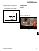
87 87a
86
85
30
Fig 382 relay pin diagram
Fig 383 xl relay
5. Disconnect voltage and multimeter leads from relay
terminals (Fig. 383).
Testing
1. Disconnect the relay from the harness.
2. Verify the coil resistance between terminals 85 and
86 with a multimeter (ohms setting). Resistance
should be from 70 to 90 ohms. There should be
continuity between terminals 87a and 30.
3. Connect multimeter (ohms setting) leads to relay
terminals 30 and 87. Ground terminal 86 and apply
+12 VDC to 85. The relay should make and break
continuity between terminals 30 and 87 when 12
VDC is applied and removed from terminal 85.
4. Connect multimeter (ohms setting) leads to relay
terminals 30 and 87a. Apply +12VDC to terminal
85. With terminal 86 still grounded, the relay should
break and make continuity between terminals 30
and 87a as 12 VDC is applied and removed from
terminal.
PTO Switch
Purpose
The PTO (Power Take Off) switch is typically used to
activate the Electric PTO Clutch and to function as part
of the safety interlock system.