
Operator's Manual


38
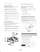
4. To make the machine move to the right, turn the knob
toward the right side of the machine; refer to Figure 46.
3
1
2
4
m–6280
Figure 46
1. Pump rod
2. Turn this way to track left
3. Tracking knob
4. Turn this way to track
right
5. To make the machine move to the left, turn the knob
toward the left side of the machine; refer to Figure 46.
6. Repeat the adjustment until the tracking is correct.
Adjusting the Caster Pivot
Bearing
Check after every 500 operating hours or at storage,
whichever occurs first.
1. Disengage the PTO, move the motion control levers to
the neutral locked position, and set the parking brake.
2. Stop the engine, remove the key, and wait for all
moving parts to stop before leaving the operating
position.
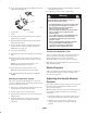
3. Remove the dust cap from the caster and tighten the
locknut (Fig. 47).
1
2
3
m–4640
Figure 47
1. Spring washers
2. Locknut
3. Dust cap
4. Tighten the locknut until the spring washers are flat,
then back off 1/4 turn to properly set the pre-load on the
bearings (Fig. 47).
Important Ensure that the spring washers are installed
correctly as shown in Figure 47.
Checking the Wheel Hub
Slotted Nut
Check after every 500 operating hours.
The slotted nut needs to be torqued to 125 ft-lb (170 N⋅m).
1. Disengage the PTO, move the motion control levers to
the neutral locked position, and set the parking brake.
2. Stop the engine, remove the key, and wait for all
moving parts to stop before leaving the operating
position.
3. Remove the cotter pin.
4. Torque the slotted nut to 125 ft-lb (170 N⋅m) (Fig. 48).
3
m–4638
1
2
4
5
Figure 48
1. Slotted nut
2. Two threads or less
showing
3. Hole in threaded shaft
4. Washer (if needed)
5. Slot
5. Check the distance from the bottom of the slot in the
nut to the inside edge of the hole.
Note: No more than 2 threads should be showing
(Fig. 48).
6. If more than 2 threads are showing, remove the nut and
install a washer between the hub and nut (Fig. 48).
7. Torque the slotted nut to 125 ft-lb (170 N⋅m) (Fig. 48).
8. Tighten the nut until the next set of slots line up with
the hole in the shaft (Fig. 48).
9. Install the cotter pin.