
Operator's Manual


17
Driving Forward or Backward
The throttle control regulates the engine speed as measured
in rpm (revolutions per minute). Place the throttle control in
the Fast position for best performance. Always operate in
the full throttle position.
The machine can spin very rapidly. The operator
may lose control of the machine and cause
personal injury or damage to the machine.
• Use caution when making turns.
• Slow the machine down before making sharp
turns.
Caution
Forward
1. Release the parking brake; refer to Releasing the
Parking Brake, page 15.
2. Move the levers to the center, unlocked position.
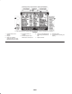
3. To go forward, slowly push the motion control levers
forward (Fig. 10).
Note: The engine will kill if the traction control levers are
moved with the parking brake engaged.
4
m–2715
3
1
2
Figure 10
1. Motion control
lever—neutral lock
position
2. Center unlock position
3. Forward
4. Backward
To go straight, apply equal pressure to both motion control
levers (Fig. 10).
To turn, release pressure on the motion control lever toward
the direction you want to turn (Fig. 10).
The farther you move the traction control levers in either
direction, the faster the machine will move in that direction.
To stop, pull the motion control levers to neutral.
Backward
1. Move the levers to the center, unlocked position.
2. To go backward, slowly pull the motion control levers
rearward (Fig. 10).
To go straight, apply equal pressure to both motion control
levers (Fig. 10).
To turn, release the pressure on the motion control lever
toward the direction you want to turn (Fig. 10).
To stop, push the motion control levers to neutral.
Stopping the Machine
To stop the machine, move the traction control levers to
neutral and separate to lock, disengage the PTO, and turn
the ignition key to Off to stop the engine. Also set the
parking brake when you leave the machine; refer to Setting
the Parking Brake, page 15. Remember to remove the key
from the ignition switch.
Important Do not engage the parking brake while the
machine is moving. Damage to the drive system may occur.
Children or bystanders may be injured if they
move or attempt to operate the tractor while it is
unattended.
Always remove the ignition key and set the
parking brake when leaving the machine
unattended, even if just for a few minutes.
Caution
Adjusting the Height of Cut
The height of cut is adjusted from 1-1/2 to 4-1/2 inch (38 to
114 mm) in 1/2 inch (13 mm) increments by relocating the
clevis pin in different hole locations.
1. Raise the height-of-cut lever to the transport position
(also the 4-1/2 inch (114 mm) cutting height position)
(Fig. 11).
2. To adjust, remove the hairpin cotter and clevis pin from
the height-of-cut bracket (Fig. 11).
3. Select the hole in the height-of-cut bracket
corresponding to the height-of-cut desired, and insert
the clevis pin (Fig. 11).
4. Secure the clevis pin with the hairpin cotter (Fig. 11).
5. Lower the height-of-cut lever onto the clevis pin.