
Operator's Manual


G014631
1
2
2
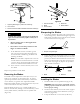
Figure53
1.Bladefronttorear
2.Measurefromthetipofthebladetotheatsurfacehere
5.Measurefromthetipofthefrontbladetotheat
surfaceandthetipoftherearbladetotheatsurface
(Figure53).Ifthefrontbladetipisnot1/16-5/16inch
(1.6-7.9mm)lowerthantherearbladetip,adjustthe
frontlocknut.
6.Toadjustthefront-to-rearbladeslope,rotatethe
adjustmentnutinthefrontofthemower(Figure54).
G014634
1
2
3
Figure54
1.Adjustingrod3.Locknut
2.Adjustingblock
7.Toraisethefrontofthemower,tightentheadjustment
nut.Tolowerthefrontofthemower,loosenthe
adjustmentnut.
8.Afteradjustment,checkthefront-to-rearslopeagain.
Continueadjustingthenutuntilthefrontbladetipis
1/16-5/16inch(1.6-7.9mm)lowerthantherearblade
tip(
Figure53).
9.Whenthefront-to-rearbladeslopeiscorrectcheckthe
side-to-sidelevelofthemoweragain;refertoLeveling
theMowerfromSide-to-Side.
RemovingtheMower
1.Parkthemachineonalevelsurfaceanddisengagethe
bladecontrolswitch.
2.Movethemotioncontrolleversoutwardtothepark
position,stoptheengine,removethekey,andwaitfor
allmovingpartstostopbeforeleavingtheoperating
position.
3.Lowertheheight-of-cutlevertothelowestposition.
4.Removethehairpincotterfromthefrontsupportrod
andremovetherodfromthedeckbracket(Figure55).
Carefullylowerthefrontofthemowerdecktothe
ground.
G014635
1
2
3
Figure55
1.Frontsupportrod3.Deckbracket
2.Lockingnut
5.Liftthemowerdeckandhangerbracketsclearof
therearliftrodandlowerthemowercarefullytothe
ground(Figure56).
35