
Operator's Manual


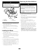


Figure37
1.Blade2.Balancer
InstallingtheBlades
1.Installthebladeontothespindleshaft(Figure35).
Important:Thecurvedpartoftheblademust
bepointingupwardtowardtheinsideofthe
mowertoensurepropercutting.
2.Installthebladestiffener,thecurvedwasher(cupped
sidetowardtheblade)andthebladebolt(Figure35).
3.Torquethebladeboltto35-65ft-lb(47-88N⋅m).
LevelingtheMowerfrom
Side-to-Side
Themowerbladesmustbelevelfromsidetoside.
Checktheside-to-sidelevelanytimeyouinstallthe
mowerorwhenyouseeanunevencutonyourlawn.
1.Parkthemachineonalevelsurfaceanddisengage
thebladecontrolswitch.
2.Movethemotioncontrolleversoutwardtothe
parkposition,stoptheengine,removethekey,and
waitforallmovingpartstostopbeforeleavingthe
operatingposition.
3.Checktheairpressureofallfourtires.Ifneeded,
adjusttotherecommendedination;referto
CheckingtheTirePressureinDriveSystem
Maintenance,page30.
4.Settheheight-of-cutlevertoposition3
[3inch(76mm)].
5.Carefullyrotatetheblade(s)sidetoside(Figure38).
G005278
1
2
2
3
3
4
4
Figure38
1.Bladessidetoside3.Measurehere
2.Outsidecuttingedges
6.Measurebetweentheoutsidecuttingedgesand
theatsurface(Figure38).Ifbothmeasurements
arenotwithin3/16inch(5mm),anadjustmentis
required;continuewiththisprocedure.
7.Attheleftsideofthemachine.Loosen,butdonot
remove,therearlockingnutonthehangerbracket
(Figure39).
8.Loosenthesidelockingnutonthehangerbracket
justenoughtoallowthecentricplatetobeadjusted
(Figure39).Usea3/8inchdriveextensionona
socketwrenchtomanipulatethecentricplate.Use
thewrenchtorepositiontheheightofthemower
deckandadjusttothedesiredheight.
9.Stopthedeckattheadjustedpositionandtighten
thesidelockingnutonthehangerbrackettohold
thenewposition(Figure39).
10.Continuelevelingthedeckbycheckingthe
front-to-rearbladeslope;refertoAdjustingthe
Front-to-RearBladeSlope.
32