
Operator's Manual


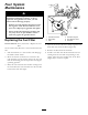


Figure30
1.Positivebatterypost
3.Red(+)chargerlead
2.Negativebatterypost
4.Black(-)chargerlead
Note:Donotrunthemachinewiththebattery
disconnected,electricaldamagemayoccur.
InstallingtheBattery
1.Positionthebatteryinthetraywiththeterminal
poststowardtheoperatingposition(Figure29).
2.Installthepositive(red)batterycabletothepositive
(+)batteryterminalusingthefastenersremoved
previously.
3.Installthenegativebatterycabletothenegative
(-)batteryterminalusingthefastenersremoved
previously.
4.Slidetheredterminalbootontothepositive(red)
batterypost.
5.Securethebatterywiththehold-down(Figure29).
6.Installtheleftsideconsole.RefertheAccessingthe
BatteryprocedureinPremaintenanceProcedures,
page22forinstructions.
ServicingtheFuses
Theelectricalsystemisprotectedbyfuses.Itrequires
nomaintenance;however,ifafuseblows,checkthe
component/circuitforamalfunctionorshort.
Fuse:
•MainF1-30amp,blade-type
•ChargeCircuitF2-25amp,blade-type
1.Raisetheseattogainaccesstothefuseholder
(Figure31).
2.Toreplaceafuse,pulloutonthefusetoremoveit
(Figure31).
G005073
1
2
Figure31
1.Main-30amp
2.Chargecircuit-25amp
29