
Operator's Manual


31
2. Move the motion control levers to the brake position,
stop the engine, remove the key, and wait for all moving
parts to stop before leaving the operating position.
3. Check the air pressure of all four tires. If needed, adjust
to the recommended inflation; refer to Checking the
Tire Pressure, page 30.
4. Set the height-of-cut lever to position D
[3 inch (76 mm)].
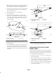
5. Carefully rotate the blade(s) side to side (Fig. 38).
Measure between the outside cutting edges and the flat
surface (Fig. 38). If both measurements are not within
3/16 inch (5 mm), an adjustment is required; refer to
steps 6 through 8.
2
3
3
1
m–6426
3
2
3
Figure 38
1. Blades side to side
2. Outside cutting edges
3. Measure here
6. Remove the hairpin cotter and washer from the leveling
bracket (Fig. 39).
7. To level the blade(s), reposition the leveling bracket(s)
in a different hole and install the washer and hairpin
cotter. (Fig. 39 and 40). A front hole lowers the blade
height and a rear hole raises its height. Adjust both sides
as required.
m–6437
4
3
1
2
Figure 39
1. Hairpin cotter and washer
2. Leveling bracket—42 inch
model shown
3. Front hole
4. Rear hole
m–6432
4
2
1
3
Figure 40
1. Hairpin cotter and washer
2. Leveling bracket—38 inch
model shown
3. Front hole
4. Rear hole
8. Check the front-to-rear blade slope; refer to Adjusting
the Front-to-Rear Blade Slope, page 31.
Adjusting the Front-to-Rear
Blade Slope
Check the front-to-rear blade level any time you install the
mower. If the front of the mower is more than 5/16 inch
(7.9 mm) lower than the rear of the mower, adjust the blade
level using the following instructions:
1. Park the machine on a level surface and disengage the
blade control (PTO).
2. Move the motion control levers to the brake position,
stop the engine, remove the key, and wait for all moving
parts to stop before leaving the operating position.
3. Check the air pressure of all four tires. If needed, adjust
to the recommended inflation; refer to Checking the
Tire Pressure, page 30.