
Service Manual


Toro®- Z Master® 8000 Series Service Manual 7-15
7
September 2016
Table of Contents
MOWER DECK AND DECK DRIVE
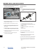
6. Remove the PTO belt tensioner spring (Figure 111)
(A) using spring removal tool P/N 92-5771.
7. Remove the PTO brake band pin and clip (B).
8. Lift the PTO handle into the engaged position.
9. Rotate the brake band fully upward.
10. On the right side of the unit, remove the two nuts
that secure the fuel access door to the frame.
Swing the door outward.
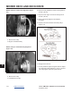
11. Remove both belts from blower drive pulley and
free the belts from the “U” guide.
12. Slide both belts off the jackshaft pulley.
13. On the left side of the unit, remove the upper belt
guide fastener.
14. Support the jackshaft assembly in current position.
15. On the left side of the unit, remove the four bolts
and washers that secure the jackshaft housing to
the frame.
16. Remove the jackshaft housing downward through
the bottom of the frame.
Installation
NOTE: The engine pulley, jackshaft pulley and
blower pulley must be aligned to prevent
belt issues.
1. Install the jackshaft assembly from underneath the
unit frame.
2. Align the jackshaft and frame mounting holes and
support the jackshaft assembly in position.
3. Install but do not tighten the four bolts and concave
washers that secure the jackshaft housing to the
frame.
NOTE: Make sure the concave washers are
installed concave side towards the frame.
4. Verify the blower housing is fully installed and all
fasteners are tight.
NOTE: The frame mounting points for the engine
and jackshaft are slotted to allow proper
pulley alignment.
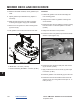
5. Align the rear pulley surfaces of the engine pulley,
jackshaft pulley, and the blower pulley using a
straight edge.
• Use the rear surface of the blower pulley as a fixed
base line.
• Loosen the mounting fasteners and slide to adjust
the position of the engine and jackshaft to attain
proper alignment of the three pulley surfaces.
• Use a straight edge to align all three rear pulley
surfaces within 1/32–1/16 in. (0.8–1.5 mm).
B
A
Figure 111