
Service Manual


HGM-H 19
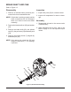
MOTOR SHAFT AND AXLE BEARING
34
33
32
31
30
27
Figure 11, Motor Shaft and Brake Disc
Refer to Figure 11
Disassembly
1. Remove all external items previously dis-
cussed in their recommended order.
2. Remove the motor shaft (34), retaining ring
(30) and gear (31) out of the middle housing
(2).
3. Remove the brake rotor (32) and the washer
(33).
4. Remove the inboard axle bearing (27).
Inspection
1. Inspect for scratches and or damage to the
brake rotor (32).
3. Inspect the gear (31) and motor shaft (34)
for wear or damage.
Assembly
1. Reassemble all parts in the reverse order
of disassembly.
2