
Operator's Manual


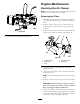

Figure19
1.Outerroller
4.Bolt
2.Spacer
5.Nut
3.Bushing
4.Selectaholesothatthecenterrollersarepositioned
tothenearestcorrespondingheight-of-cutdesired
(Figure19).
Note:Donotadjusttherollerstosupportthe
mowerhousing.
5.Installthecenterrollers,bushing,spacer,bolt,and
nut(Figure19).
6.Torquetheboltto40to45ft-lb(54to61N⋅m).
AdjustingtheFlowBafe
Themowerdischargeowcanbeadjustedfordifferent
typesofmowingconditions.Positionthecamlocks
andbafetogivethebestqualityofcut.
1.DisengagethePTO,movethemotioncontrol
leverstotheneutrallockedpositionandsetthe
parkingbrake.
2.Stoptheengine,removethekey,andwaitforall
movingpartstostopbeforeleavingtheoperating
position.
3.Toadjustthecamlocks,swingtheleverupto
loosenthecamlock(Figure20).
4.Adjustthebafeandcamlocksintheslotstothe
desireddischargeow.
5.Swingtheleverbackovertotightenthebafeand
camlocks(Figure20).
6.Ifthecamsdonotlockthebafeintoplaceoritis
tootight,loosentheleverandthenrotatethecam
lock.Adjustthecamlockuntilthedesiredlocking
pressureisachieved.
Figure20
1.Camlock
3.Rotatecamtoincreaseor
decreaselockingpressure
2.Lever
4.Slot
PositioningtheFlowBafe
Thefollowingguresareonlyrecommendationsfor
use.Adjustmentswillvarybygrasstype,moisture
content,andheightofgrass.
Note:Iftheenginepowerdrawsdownandthemower
groundspeedisthesame,openupthebafe.
PositionA
Thisisthefullrearposition.Thesuggesteduseforthis
positionisafollows.
•Useforshort,lightgrassmowingconditions.
•Useindryconditions.
•Forsmallergrassclippings.
•Propelsgrassclippingsfartherawayfromthe
mower.
Figure21
PositionB
Usethispositionwhenbagging.
22