
Service Manual


118 PW / PY Series
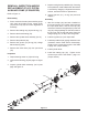
Refer to Figure 11.
Disassembly
1. Prior to removal of the 6cc piston auxiliary pump
(40), mark the auxiliary pump, charge pump
(41) and end cap (25) for correct alignment at
assembly.
2. Remove the rotating cap (78) and O-ring (77).
3. Remove the thrust bearing (76).
4. Remove the cylinder block assembly (72-75).
5. Remove the portblock (40).
6. Remove the gerotor (41),O-ring (39), charge
ball and spring (44A).
7. Remove the relief valve (70) from port block
(40).
Inspection
1. Inspect bearing areas on (78) and O-ring.
2. Inspect thrust bearing (76) see page 121 gure
14.
3. Inspect cylinder block assembly (72-75) see
page 120 gure 13.
REMOVAL, INSPECTION AND/OR
REPLACEMENT OF 6CC PISTON
AUXILIARY PUMP (IF EQUIPPED)
Figure 11.
4. Inspect running face on portblock (40). Grooving
in the portblock, made evident when the surface
is checked by dragging a ngernail across the
surface, would be cause for replacement.
5. Inspect gerotor (41), O-ring (39) and end
cap(25).
Assembly
1. After the endcap (25) has been installed on
the pump housing (15). Position the pump with
the input shaft down, and the end cap (25)
horizontal. Place the charge ball (44) in the end
cap (25) charge passage so the ball mates to
the end cap (25) charge ball seat. Place the
charge spring (44), on top of the charge ball.
2. Insert the gerotor (41) over input shaft.
3. Install the portblock (40) paying attention to the
orientation marks made before disassembly.
Tighten to the correct torque value. See Table
2, page 110. (Torque Values.)
4. Install cylinder block.
5. Install the rotating cap (78). Tighten to the
correct torque value. See Table 2, page 110.
(Torque Values.)
15
25
39
41
158
70
166
40
158
167
58
56
71
72
73
74
75
76
77
78
79
44A