
Service Manual


4-6 Z Master 500 Gas Series Service Manual
4
HYDRAULIC SYSTEM
Fig 115 DSC-3067
Fig 117 DSC-2986
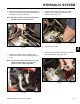
7. Align the outer edge of the hydrostatic pump pulley,
using a straight edge, to the outer edge of the
engine drive pulley (Fig. 115). Tighten the two set
screws once alignment is achieved.
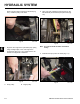
9. Install the seat prop rod to the frame (Fig. 117).
Fig 116 DSC-3068
Fig 114 DSC-3066
8. Using a pry bar, release the spring tension on the
idler assembly and install the pump drive belt (Fig.
116).
Apply some anti-seize compound to the shaft (Fig.
114). Install the pulley to the shaft.
Note: The engine shield has been removed for
clarity.
A
B
A. Pump pulley B. Engine pulley