
Service Manual


4-3Z Master 500 Gas Series Service Manual
4
HYDRAULIC SYSTEM
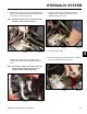
6. Remove bolt, washer, and nut located between ball
joint and control arm that retains the tracking link rod
to the hydro control arm (Fig. 103).
Note: It may be necessary to move the hydro lever
forward in order to remove the bolt.
Fig 103 DSC-2994
7. Remove the two high pressure hydraulic lines,
located at the bottom of the hydrostatic pump (Fig.
104).
Note: Cap the hose and the tting to prevent entry
of dirt and debris. Mark or tag one of the
hoses to ensure correct reassembly.
Fig 104 DSC-2996
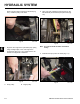
Fig 106 DSC-2999
9. Remove the pump suction hydraulic line, located on
top of the hydrostatic pump (Fig. 106).
Fig 105 DSC-2998
8. Remove the hose clamp around the case drain
hydraulic hose, located on the left side of the
hydrostatic pump (Fig. 105).
A
A. Case drain hose clamp