
Operator's Manual


9.Applyslightrearwardpressureonthemotion
controllever,turntheheadoftheadjustmentbolt
intheappropriatedirectionuntilthecontrolleveris
centeredintheneutrallockposition(Figure57).
Note:Keepingrearwardpressureontheleverwill
keepthepinattheendoftheslotandallowthe
adjustmentbolttomovethelevertotheappropriate
position.
10.Tightenthenutandjamnut(Figure57).
11.Repeatfortheoppositesideofthemachine.
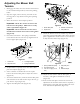
Figure57
1.Clevispininslot7.Spring
2.Nutagainstyoke
8.Pivotshaft
3.Adjustmentbolt9.Yoke
4.Pumprod10.Locknut
5.Doublenuts11.Balljoint
6.Jamnut
HydraulicSystem
Maintenance
CheckingtheHydraulicFluid
ServiceInterval:Aftertherst8hours
Every25hours
FluidType:Mobil115W-50syntheticmotoroilor
equivalentsyntheticoil.
Important:Useoilspeciedorequivalent.Other
uidscouldcausesystemdamage.
HydraulicSystemOilCapacity:67oz.(2.0l)
Note:Therearetwowaysofcheckingthehydraulicoil.
Oneiswhentheoiliswarmandoneiswhentheoilis
cold.Thebafeinsidethetankhastwolevelsdepending
iftheoiliswarmorcold.
1.Positionthemachineonalevelsurfaceandsetthe
parkingbrake.
2.Cleantheareaaroundllerneckofhydraulictank
(Figure58).
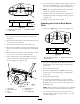
Figure58
1.Cap3.Colduidlevel-full
2.Bafe4.Hotuidlevel-full
3.Removethecapfromthellerneck.Lookinsideto
checkifthereisuidinthereservoir(Figure58).
4.Ifthereisnouid,adduidtothereservoiruntilit
reachesthecoldlevelofthebafe.
5.Runthemachineatlowidlefor15minutestoallow
anyairtopurgeoutofthesystemandwarmthe
uid.RefertoStartingandStoppingtheEnginein
Operation,page13.
6.Rechecktheuidlevelwhiletheuidiswarm.The
uidshouldbebetweencoldandhot.
7.Ifrequired,adduidtothehydraulictank.
Note:Theuidlevelshouldbetothetopofthehot
levelofthebafe,whentheuidishot(Figure58).
8.Installcaponllerneck.
43